LT6502 is assembled
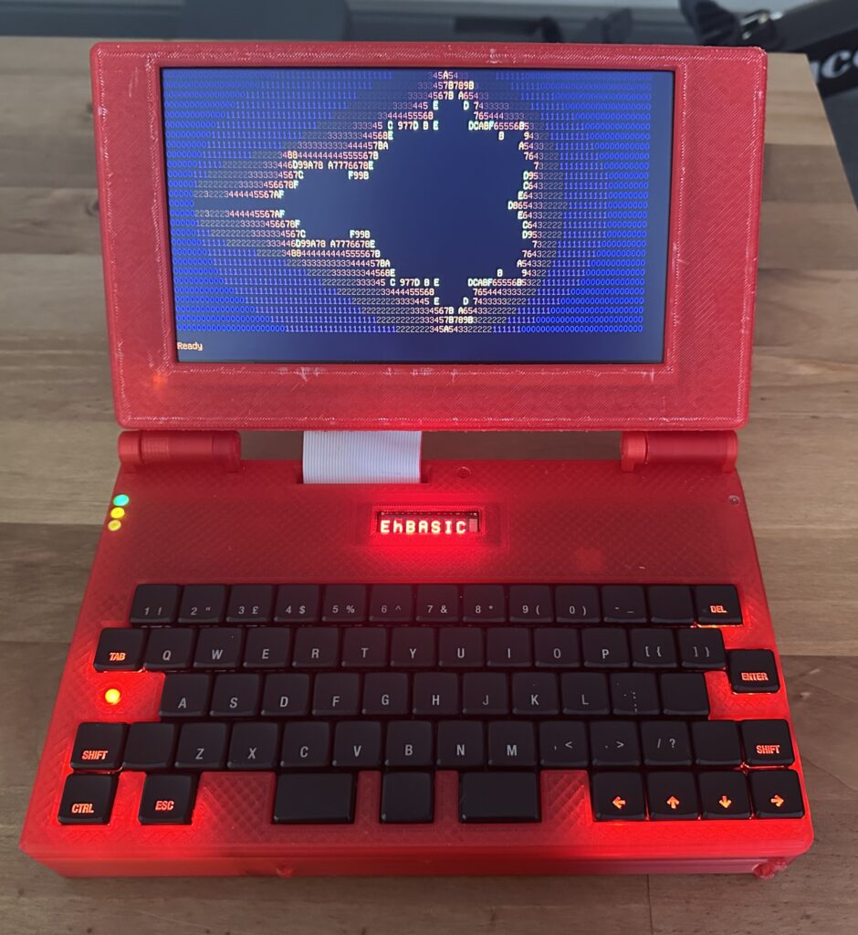
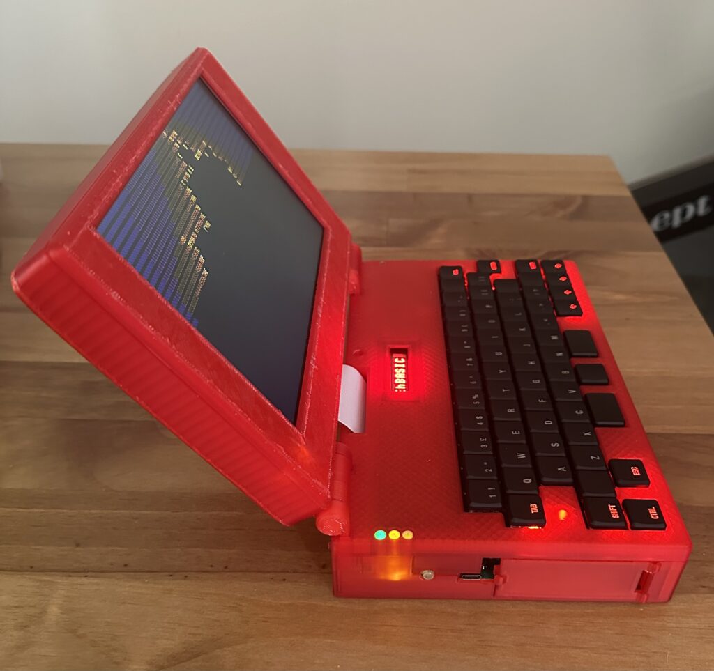
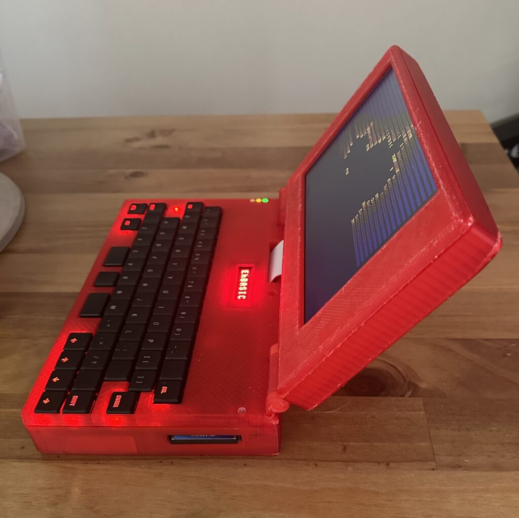
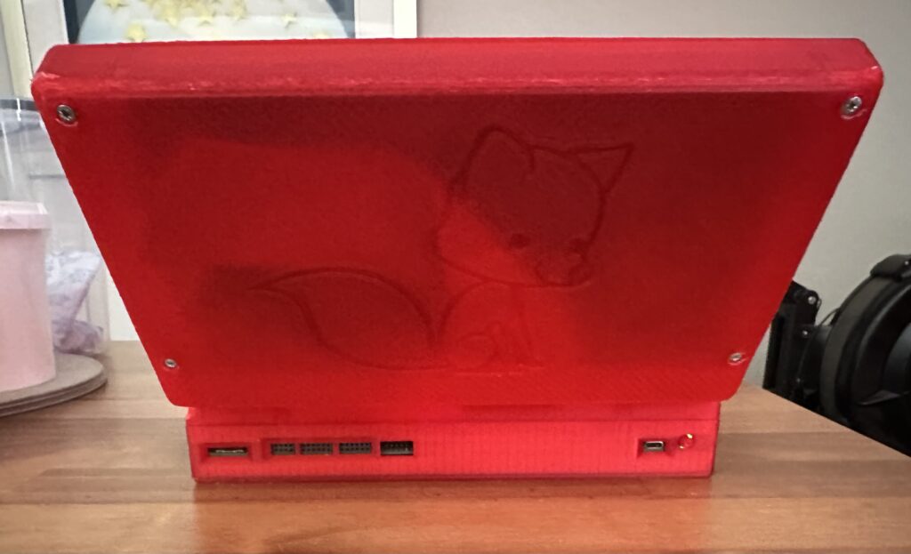
I give you the very chonky 6502 based laptop;
It has been quite the challenge to get this up and running, the main challenges code wise were;
1) Getting the screen to work, and getting scrolling to work (that was way more effort than I thought it would be).
2) Understanding EhBASIC and how it works so that I could add in extra commands.
Talking of which here are the commands I’ve added;
- BEEP P,L – Pitch (P) is 0-255, length (L) = 0 to 255
- CIRCLE X,Y,R,C,F – Draws a Circle, X is 0-799, Y is 0-479, R(radius) is 1 – 65535, C is 8bit RGB Value (RRRGGGBB), F is fill (0 = no fill, 1 = fill)
- CLS – Clear screen (both graphic and text mode)
- COLOUR <0-255> – Sets the colour (text) to 8bit RGB value, in the form RRRGGGBB
- CURSOR X,Y – Sets the cursor position (in characters)
- DIR – Scans the Compact Flash card and shows slot number and name for any files present
- ELIPSE – X,Y,RX,RY,C,F – Draws an elipse, X is 0-799, Y is 0-479, RX is X radius, RY is Y radius, C is colour and F is fill
- LINE X,Y,EX,EY,C – Draws a line, X is 0-799, Y is 0-479, EX is X end point (0-799), EY is Y end point (0-479), C is colour
- LOAD <0-2047> – LOAD a file from CF
- MODE <0,1> – Sets the display mode, MODE 0 is text, MODE 1 is graphics
- OUTK – Outputs Text to the 8 character display on the keybed, can be a string or value, anything more than 8 characters will result in text shifting. a String will clear the display and then output the characters
- PLOT X,Y,C – Plots a dot, X is 0-799, Y is 0-479 and C is 8bit RGB Value (RRRGGGBB)
- SAVE <0-2047>,”” – SAVE current BASIC program into a SLOT and give it a name, upto 16 characters
- SQUARE – X,Y,EX,EY,C,F – Draws a square, X is 0-799, Y is 0-479, EX is X end point (0-799), EY is Y end point (0-479), C is colour and F is fill
- WOZMON – Jumps to wozmon, Q will exit WOZMON and return to basic (Handy for check chunks of memory)
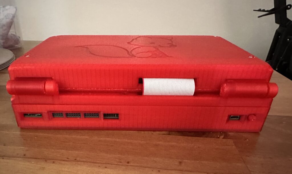
The biggest challenge of all for me was the case, what you is the 3rd or 4th revision of most parts. The hinges in particular were incredibly difficult.
The hinges were inspired by this print – https://www.printables.com/model/658393-friction-hinge-mechanism/comments#preview.file.aPNjd. It took a bit of fiddling and experimenting to get it right.
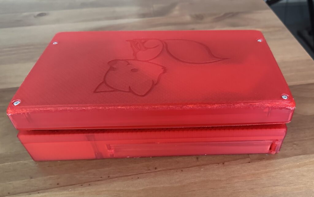
The case could do with reprinting, but I’ve used up two 1Kg reels of translucent red filament and have only a few grams left, so I can’t. Next time we order some filament I may get some more and give it a go.
But for my first real go at a 3D design (and a complex one at that) I’m pretty happy. I’ve learned a lot about 3D design and printing.
So, what would I do differently? a number of things;
- Start the design with the keybed, it’s a bit squeezed in (I’m not happy with the placement of a few keys), basically I made the main PCB then tried to squeeze in the keyboard, oops.
- Spend longer sourcing a thinner battery (this is 3x18650s), the base is very thick and this is largely down to the thickness of the battery pack.
- Use an FFC for the display (this would make the display portion about 10mm thinner straight away!)
- Reduce the number of smaller fiddly bits in the case. A lot of the problems I had were down to me trying to print things with 0.1mm resolution.
- Add more clips for the case so it doesn’t gape in places (front bezel around the display isn’t good)
- Electronics wise, I’d add an internal expansion port in addition to the slot at the front. Just for simple things.
- Perhaps having some pageable RAM would be neat again, perhaps via an expansion
- I’d probably do more with the USBC-PD, a buck/boost converter so I could get the most power from the USBC-PD, instead of forcing USBC-PD to 5V and then requesting various currents, I’m missing an opportunity to get more power, change charging speed, etc.
- Software wise, I would’ve liked to get a FAT16 implementation working, but that’s honestly a bit beyond me and the FAT32 examples seem to use a LOT of ROM (>8KByte).
- I would also have liked to get the 10″ screen working as the 9″ is a little small, however it uses a different driver IC which has very little in the way of documentation sadly.
The onboard RA8875 display driver is connected via 8bit parallel bus and works great, it’s very quick to do things like lines, circles, elipses, squares, etc. It can be a bit fiddly to get working, but when it works, it’s great.
Next I want to add a wifimodem (front expansion slot) and possibly some kind of FPU for speeding up the math I want to do with this (mostly fractal experiments).
I will try and do a video at some point, not sure when, I’ll post a link here when I do.