PC6502 update
I have been tinkering with various bits of the PC6502 computer system in between looking after Suzi (who is getting better slowly, but we still have a couple of months of hard work ahead of us).
Previously I was able to show the OPL3 Sound and Speech card working, Here is an updated video of it playing a tune 🙂
Next I managed to get the display working, this is a 480×272 screen, it has built in fonts and a bunch of features line circle, line drawing and filling, so I can do a bunch of cool things as I go forward with it.
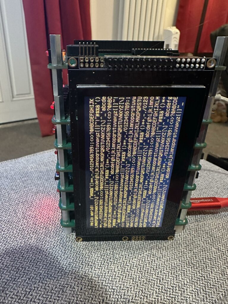
I’ve not figured out how to rotate it yet, but that should be fairly straight forward.
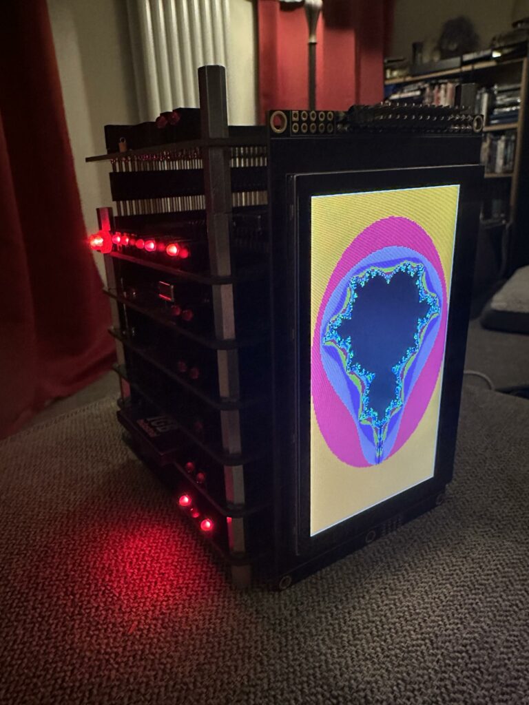
And, of course, I had to do a mandlebrot as I now have colour!
The other things this board does is provide a 6551 serial interface to connect a keyboard to, which I’m now happy to say is working.
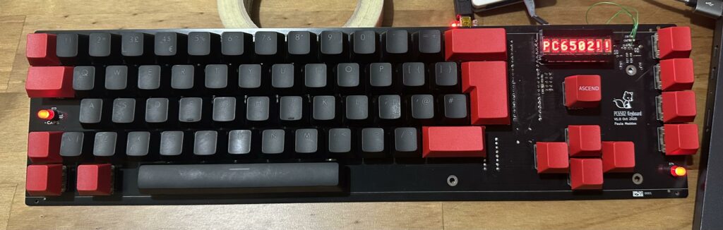
I’ve not yet integrated this into the firmware, so you can peek/poke from BASIC and it behaves fine.
Next I’m in the middle debugging a transputer link interface for it. Because, why not? It’s not fully working yet, I need to tweak the timing of the access to the Inmos C011 Link adapter IC. But it’s getting there.
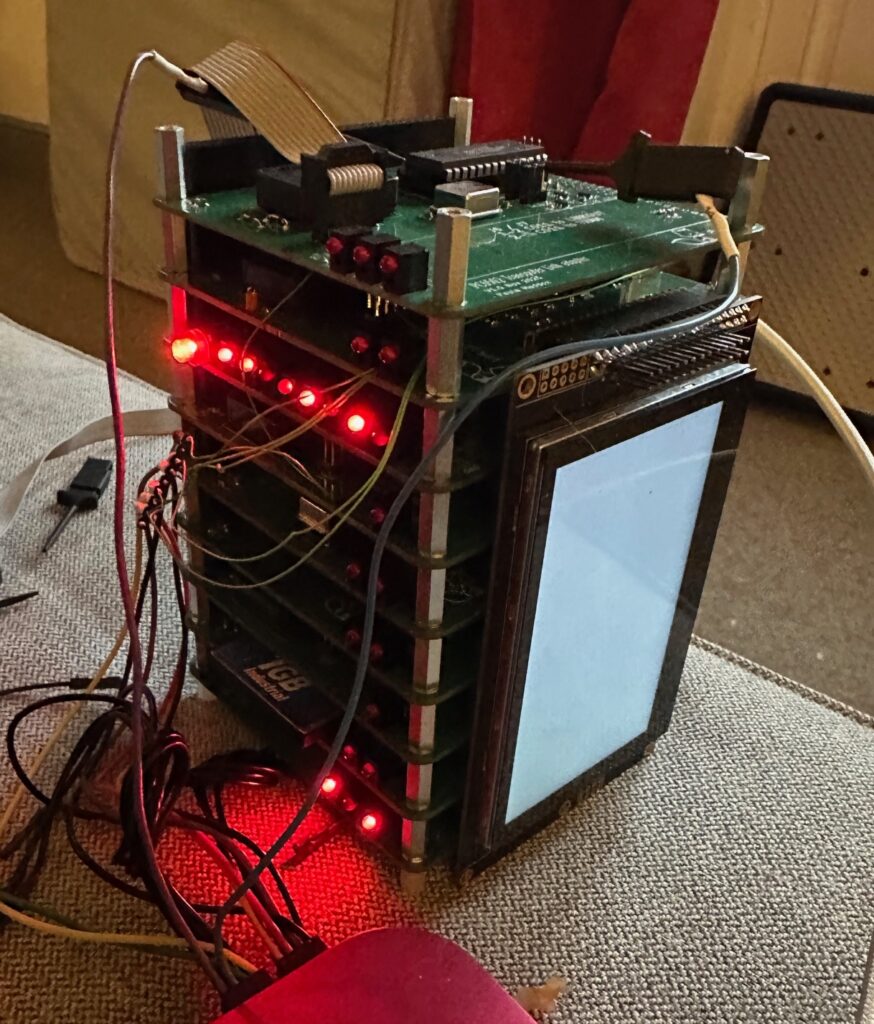
The stack as it stands (top to bottom) is;
- Inmos C011 Link adapter (with space for a single Transputer TRAM)
- Display/Keyboard card
- 6502 CPU board (with ROM/RAM/console)
- 6522 VIA (B)
- Speech and OPL3 sound card
- Dual SPI card
- 6522 VIA (A)
- Compact Flash
- Power supply card
Now, all this got me thinking…..
I have a 6502 running EhBASIC, a graphical/text display a keyboard, via and compact flash. So what if I made a laptop?
So, well, errr, I have begun that. Here are some renders.
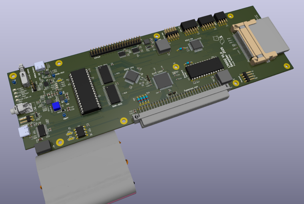
First here is the main board, with CPU, ROM, RAM, Console port (USBC), Serial port (6551), compact flash, VIA and also battery and charging circuit. Oh and an expansion connector.
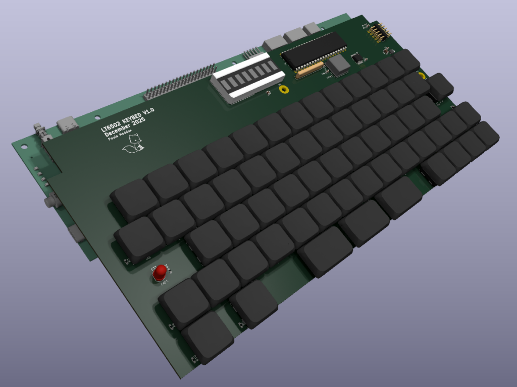
The keyboard (below) sits on top of this and slightly forward so it sits above the battery.
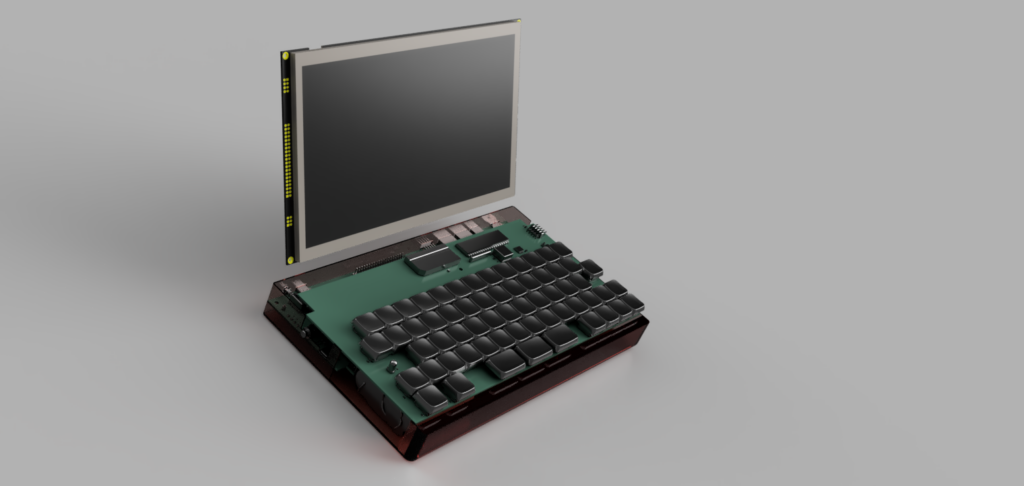
So, we of course need a screen, this time 10″, 1024 x 600 and it should work something like this
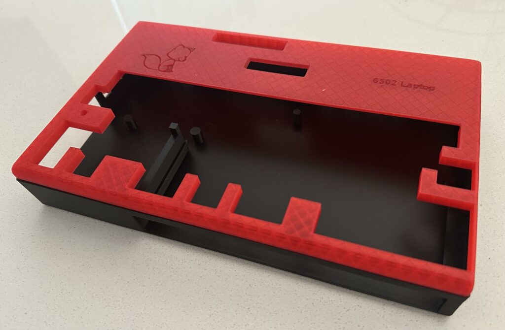
And here is 3D print of the first part of the case (lower part in black, upper in translucent red);
And here is a render of the whole thing with the lid closed (viewed from the rear left).
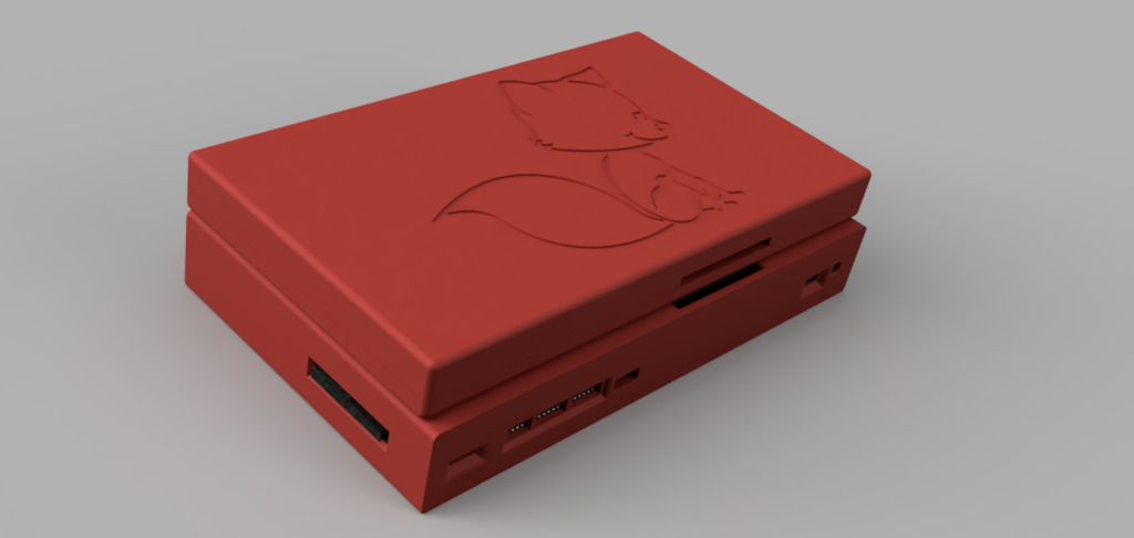
You can see the compact flash card on the left, a slot for the volume control thumb wheel, VIA ports, JTAG port for main CPLD Glue Logic and USB port for charging.
The long hole on the top of the base, and back of the lid, is for the 40 pin IDC going between the base and the lid for the display.
Now I’m not a mechanical engineer, so this isn’t “sleek”, it’s about 50mm thick in total. The bit I’m struggling with at the moment is the hinges. What I need are “torque” or “friction” hinges. I’ve worked out I need something around 0.3Nm (based on an online calculator I found). Now finding these is proving extremely difficult and trying to find them with drawings/models is adding to the challenge.
I have ordered the PCBs for the 6502 Laptop, so whilst they’re being made I can work on locating suitable hinges.